In industrial fluid piping networks—spanning water treatment, oil and gas, chemical processing, and district heating—the check valve (also known as a non-return valve or one-way valve) serves as the critical, ultimate mechanical line of defense safeguarding the entire infrastructure.
As a completely self-acting mechanical device, a check valve relies entirely on the kinetic energy of the media and the reverse pressure differential within the pipeline to open and close. Requiring no external pneumatic air, electricity, or manual actuation, it maintains autonomous unidirectional flow protection even during catastrophic plant-wide power blackouts. However, in the field, a lack of understanding regarding their internal kinematics often leads to improper specification and premature failure. This guide explores the core functions of check valves, the anatomy of their primary classifications, and how to eliminate the most common field failure modes.
1. Core Functions and System Protection Mechanisms
In high-pressure and complex industrial fluid infrastructure, check valves perform four primary engineering functions:
- Eliminating Water Hammer and Protecting Pump Assets: When a pump or compressor experiences a sudden shutdown, the fluid column within the pipeline instantly loses forward momentum and reverses direction. This high-velocity backflow crashes into the pump, causing impeller reversal, which frequently shears drive shafts and burns out motors. Concurrently, the abrupt deceleration of the fluid column generates water hammer. These hydraulic shockwaves transmit severe vibrations through the piping network, capable of rupturing flanged joints and tearing down pipe supports. A fast-closing check valve seals the line the exact millisecond flow velocity hits zero, blocking reverse momentum before devastating pressure surges can develop.
- Preventing Backflow and Cross-Contamination: In multi-chemical processing or municipal water distribution grids where various lines converge, a localized pressure drop on an upstream header can cause hazardous wastewater or chemicals to backflow into clean utility or potable water lines. Check valves establish an absolute physical barrier at these cross-connections to eliminate contamination risks.
- Maintaining Pipeline Pressure Stability: In complex networks with parallel branches (such as multiple boilers connected to a common steam header), a shutdown or pressure drop in a single branch would normally cause the main header to bleed pressure backward into that offline line. Check valves strictly enforce unidirectional flow logic, maintaining steady pressure zones across online process segments.
- Minimizing Fugitive Emissions and Micro-Leaks: By intercepting reverse high-pressure surges before they slam into downstream control and isolation valves, check valves mitigate mechanical fatigue on packing seals, effectively lowering localized medium leakage throughout the asset lifecycle.
⚠️ Industrial Sealing Insight
Unlike isolation valves (such as gate or ball valves) that utilize external actuators or handwheels to force a tight seal via mechanical torque, a check valve relies entirely on reverse hydrostatic line pressure to wedge the disc against the seat. Due to this structural constraint, international testing standards like
MSS SP-61permit slightly higher allowable seat leakage rates for check valves than for on/off valves.For low-pressure gas or clean utility services where bubble-tight shutoff (zero leakage) is mandatory, engineers must specify elastomeric soft seats (e.g., Buna-N, Viton, or PTFE). For ultra-high-temperature, high-pressure, or abrasive slurry services, a metal-to-metal hard seal is required, which may exhibit microscopic weeping at near-zero backpressures.
2. Four Major Classifications and Internal Structural Anatomy
Because fluid systems vary drastically in通径 (bore size), pressure, viscosity, and velocity gradients, check valves are engineered in four primary structural configurations. No single design is universal; a check valve’s internal anatomy directly dictates its operational kinematics and application limits.
1. Swing Check Valves
- Internal Anatomy: A swing check valve primarily consists of a valve body, bonnet, disc, and a hinge pin paired with a disc arm spanning across the top of the valve cavity. The disc has no center-guiding stem; instead, it hangs freely from the hinge pin like a swinging trapdoor.
- Operational Mechanics: As forward flow enters the valve, its kinetic energy pushes against the disc, forcing it to rotate upward around the hinge pin until the disc arm rests firmly against the internal mechanical stop. When the flow slows down or reverses, the disc relies on its own weight and the reverse hydrostatic line pressure to swing back down in an arc, sealing tightly against the valve seat.
- Engineering Trade-offs: It features a full-bore, straight-through flow path that maximizes the flow coefficient ($C_v$) and minimizes pressure drop, while remaining fully compatible with pipeline pigging devices (piggable). However, because the disc must travel a long distance from full-open to full-close, its closure response is relatively slow. In high-dynamic lines with sudden flow reversals, it is highly susceptible to generating severe slamming water hammer. Structurally, it is restricted to horizontal installations or vertical lines with flow moving upward.
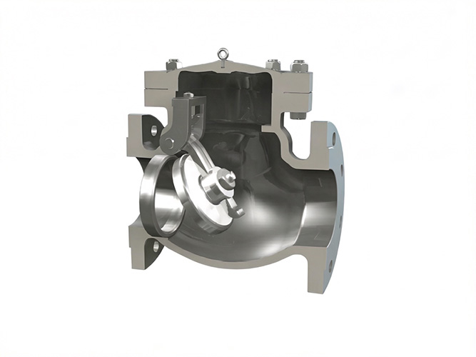
Internal structure diagram of a swing check valve showing disc, hinge pin, and body.2. Lift Check Valves
- Internal Anatomy: The internal fluid path of a lift check valve forms an “S-shape” similar to a globe valve. Its core internals include a body guide seat with a precision alignment sleeve, a plunger-shaped poppet disc equipped with a guiding stem, and a high-performance assistance spring coiled around the stem.
- Operational Mechanics: Forward line pressure enters from beneath the valve seat, overcoming the spring pre-load and disc weight (the cracking pressure) to push the disc upward in a parallel, linear guided alignment movement. The moment the forward velocity begins to decelerate, the internal spring instantly releases its tension, driving the poppet disc vertically back onto the seat fractions of a second before reverse flow can gather momentum.
- Engineering Trade-offs: It acts as a highly efficient silent check valve. The short travel stroke combined with spring-assisted quick-closure ensures a non-slam shutoff at zero velocity, effectively suppressing water hammer. However, the tortuous “S-shaped” path incurs a significantly higher pressure drop than swing checks. Additionally, the tight tolerances between the guiding stem and sleeve make it unsuitable for dirty, scaling, or particulate-laden media, which can easily cause internal mechanical jamming.
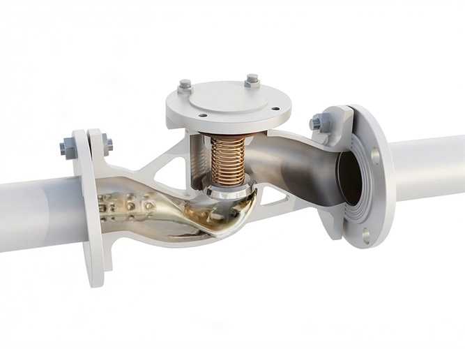
Internal structure of lift check valve with vertical lift mechanism.3. Dual Plate Wafer Check Valves
- Internal Anatomy: This represents an ultra-compact, short face-to-face design. Breaking away from traditional single-disc architecture, its internal trim features two symmetrical, semi-circular plates (dual plates), a central hinge pin splitting the flow bore, and a pair of heavy-duty torsion springs. The valve body lacks bulky end-flanges, appearing as a thin wafer ring.
- Operational Mechanics: When forward flow passes through, the fluid pressure forces the two semi-circular plates to fold inward toward the central hinge pin axis like a butterfly folding its wings. As the flow stops or begins to reverse, the central torsion springs instantly deliver high torque, forcing the dual plates to snap outward, flattening against the seat faces to achieve a rapid dual-barrier block.
- Engineering Trade-offs: Its face-to-face dimensions are incredibly short, making its weight only 20% to 30% of an equivalent flanged swing check valve, which drastically cuts down on spatial footprint and structural piping supports. Furthermore, its spring-assisted non-slam quick closing profile provides excellent water hammer prevention. It is also the only configuration that functions reliably in vertical down-flow lines (when specified with heavy-duty customized springs).
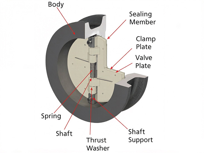
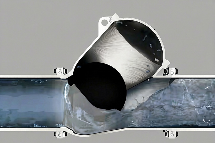
Cross-section of dual plate check valve with plates in fully open position.4. Ball Check Valves
- Internal Anatomy: This design features the most elementally pure internal mechanics. The valve cavity is engineered with an inclined rolling track and a conical seat, while the closure element consists solely of a free-floating, completely unconstrained solid or hollow ball. Certain variants include an anti-dislocation cage, but it contains no springs, pins, or bearings.
- Operational Mechanics: When forward flow enters from below, it lifts the ball and pushes it up along the inclined track, allowing fluid to wrap around the sphere and stream downstream. When the pump shuts down and flow reverses, gravity and backpressure cause the ball to roll back down the track, dropping precisely into the conical seat to form a tight seal.
- Engineering Trade-offs: The fluid momentum forces the ball to spin continuously during operation. This rotation creates a unique wiping and self-cleaning action that constantly scrapes away viscous buildup, sticky polymers, or mineral scale from the seating surfaces, making it virtually immune to jamming. It is highly recommended for high-viscosity, slurry-heavy, or wastewater applications, though it incurs a higher pressure drop in smaller line sizes.
Internal structure diagram of a ball check valve showing ball lifted off the seat in open position.3. The Critical Pitfall: Kinematics and Destructive Impact of Valve Chatter
In field pipeline management, up to 90% of premature check valve failures are not caused by manufacturing defects, but by a systemic sizing error: blindly selecting a check valve based strictly on pipeline diameter (line size).
While on/off isolation valves suffer no internal wear regardless of whether fluid velocity is low or high, a check valve trim is a flow-dependent dynamic mechanism. To hold a check valve 100% stable in the fully open position, the forward fluid velocity must generate enough kinetic dynamic lift to pin the internal disc firmly against its mechanical stop.
If a check valve is sized equivalent to a 10-inch pipeline simply because it matches the pipe flanges, but the actual process flow operates at a low velocity, the fluid’s kinetic energy will be insufficient to hold the disc open. The disc will hover mid-stream, trapped in a violent tug-of-war between the internal spring counter-force and localized fluid turbulence. This rapid, repetitive mechanical oscillation is known as valve chatter.
Valve chatter triggers a sequence of destructive failures across the system:
- Trim Fatigue Fracture: Components like a swing check’s hinge pin, a lift check’s guiding sleeve, or a dual plate’s torsion spring undergo severe high-frequency wear and friction under chatter conditions, leading to rapid mechanical fatigue failure. It mirrors a building door caught in a gale; the hinges will fracture first.
- Downstream Debris Migration: Severe chatter causes the disc arms or internal pins to snap, allowing the entire disc assembly or metallic shards to break away. These fragments migrate downstream at high velocities, where they can shred downstream control valve trim, jam multi-stage centrifugal pump impellers, or puncture analytical flow meters.
- Unpredicted System Pressure Drops: When stuck in a partially open, chattering state, the valve’s effective operating flow area is significantly restricted. This induces intense localized turbulence and pressure losses far exceeding theoretical calculation sheets, forcing upstream pumps to draw more power.
4. Sourcing Criteria and On-Site Installation Matrices
🛠️ The Golden Installation Rule: 10D Upstream Straight Pipe Run
To ensure check valve internals receive stable, uniform, and laminar flow, it is highly recommended to maintain a minimum of 10 pipe diameters (10D) of uninterrupted straight pipe run upstream of the valve.
Bolting a check valve directly downstream of turbulence-inducing components—such as elbows, T-junctions, or throttling valves—subjects the internal disc to asymmetric fluid shear forces. This non-uniform flow profile triggers rapid eccentric wear and localized chatter. Adhering to the 10D rule is a prerequisite for achieving the rated design lifecycle of any check valve style.
📋 Pipeline Check Valve Specification and Troubleshooting Matrix
| Process Profile / Symptom | Root Structural Cause | Recommended Sourcing & Engineering Solution |
| High-Head Pump Discharges / Severe Water Hammer Risk | Fluid velocity reverses too quickly for a long-travel, slow-closing swing check valve, causing the disc to slam into the seat at peak reverse velocity. | Specify a fast-closing, spring-assisted silent lift check valve or a dual plate wafer check valve to ensure closure at zero velocity. |
| Piping Grids Operating under Constant Low-Velocity Conditions | Blind line-size sourcing results in insufficient kinetic lift to pin the disc open, causing violent internal trim chatter. | Re-calculate process flow profiles and source a reduced-port check valve (lower $C_v$) to increase localized velocity, or specify a customized heavier internal spring. |
| Space-Constrained Skids / Weight-Restricted Piping | Traditional flanged swing or lift check valves are too bulky, introducing heavy bending stress on elevated headers. | Source a dual plate wafer check valve; its ultra-short face-to-face profile trims total component weight by over 70%. |
| Media Carrying Mineral Scale, Solids, or High Viscosity | Precision-guided stems (lift style) or centralized springs (dual plate style) will jam due to particulate accumulation. | Specify an unobstructed, full-bore swing check valve or a self-cleaning ball check valve, and deploy an upstream strainer. |
| Pipelines Formatted in a Vertical Down-Flow (Flow Down) Orientation | Media flow aligns with gravity; standard gravity-closed check valves hang open and fail to form a backflow seal. | You must uniquely source a spring-loaded lift or dual plate check valve engineered with customized heavy springs to overcome gravity. |
5. Conclusion: Achieving Genuine Mechanical Asset Integrity
In summary, a check valve should never be dismissed as an unreliable commodity or a frequent maintenance liability; it is the vital guardian protecting pumps and piping grids from water hammer, reverse rotation, and cross-contamination. When operators complain that “check valves fail to work long-term,” the root cause rarely lies within the valve’s manufacturing quality, but rather in a historical failure to align the system’s fluid dynamics with the valve’s internal mechanical structure.
Achieving true mechanical asset integrity requires a return to precise engineering specifications. First, engineers must abandon the habit of sizing valves based strictly on pipe diameters and instead calculate actual fluid velocity to select the correct internal profile (e.g., specifying low-pressure-drop swing checks for high-volume lines, or spring-assisted dual plates for shock-prone grids). Second, the 10D upstream straight pipe run must be strictly enforced to eliminate the turbulent flow profiles that feed valve chatter. By matching internal trim physics to actual process line conditions, check valves will shed their problematic reputation and consistently deliver autonomous, long-term security across your industrial fluid infrastructure.