For piping engineers, plant operators, and industrial procurement managers, Piping and Instrumentation Diagrams (P&IDs) are the universal language of the process industries. At the heart of these complex technical blueprints are valve symbols.
Valves are the active regulators of flow, pressure, and temperature within fluid systems. Misinterpreting a single symbol on a schematic can lead to catastrophic sizing errors, costly compliance failures, improper installation on the plant floor, or severe safety hazards. This comprehensive guide breaks down the essential valve symbols you need to master, spanning international standards like ISA/ANSI 5.1, ISO 10628, and PIP (Process Industry Practices).
1. The Anatomy of a Valve Symbol: The “Bowtie” Base
Before diving into specific valve types, it is crucial to understand how a standard valve symbol is constructed. Most symbols start with a basic “bowtie” shape (two equilateral triangles meeting at a single point), which represents the valve body and the fluid flow path.
To specify how the valve operates, engineering standards add modifiers to this base: shapes on top represent the actuator (driving mechanism), internal details indicate the trim or disc nature, while lines on the borders indicate the end connections.
2. Core Valve Symbols and Mechanical Profiles
Different valve designs serve distinct purposes—either isolating the flow, throttling the velocity, or protecting downstream equipment from overpressure. Below are the standard symbols alongside their real-world mechanical behaviors.
Isolation & On-Off Valves
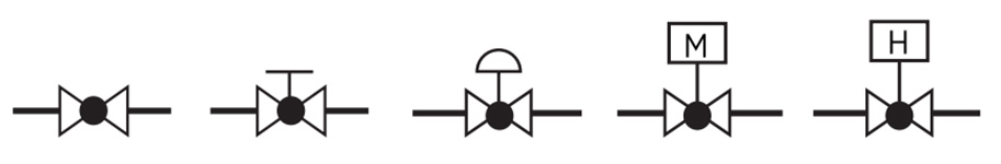
Gate Valves
The gate valve is the workhorse of fluid isolation. On a P&ID, its symbol is the classic enclosed bowtie with two vertical bounding lines. Mechanically, it uses a linear wedge or disc that moves up and down perpendicular to the flow stream. Because it offers zero resistance and minimal pressure drop when fully open, the symbol represents a straight-through, unrestricted pathway. It is strictly used for fully open or fully closed service.
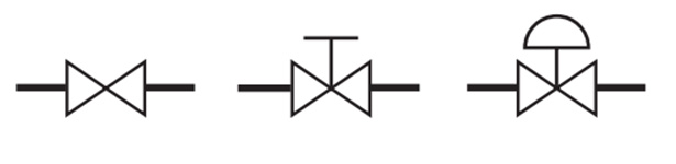
Bare Gate Valve, Hand-Operated (Manual) Gate Valve, and Pneumatic Diaphragm Actuated Gate Valve
Ball Valves: Full Port vs. Reduced Port
Ball valves are highly favored for quick, quarter-turn isolation. The P&ID symbol features a bowtie with an open/hollow circle in the center, mimicking the bored ball inside the valve body.
When reviewing system blueprints, pay close attention to the flow path specification notes. A Full Port (Full Bore) ball valve maintains an inner diameter equal to 95% or more of the pipeline’s nominal pipe size, ensuring zero flow restriction and allowing pigging operations.
A Reduced Port (Reduced Bore) valve narrows down to an internal diameter of 85% or less of the pipeline’s nominal pipe size, which increases flow resistance and pressure drop but offers a lighter weight and optimized cost for gas or water-like media.
Butterfly Valves
Used frequently in large-diameter water treatment, desalination, and utility lines, the butterfly valve symbol consists of two vertical parallel lines with a diagonal line passing through the center point, representing the rotating disc. They excel in tight locations where space is limited.
Throttling & Flow Control Valves
Globe Valves
Unlike gate valves, globe valves are designed specifically for regulating and throttling fluid flow. To differentiate it from a ball valve, the globe valve symbol features a solid, filled black circle in the center. This solid dot hints at the tortuous “S-shaped” fluid path inside, which creates an inherent pressure drop but allows for precise flow adjustments without inducing severe cavitation or erosion.
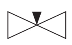
Needle Valves
For extremely fine flow calibration (such as sampling lines or chemical injection skids), engineering diagrams use the needle valve symbol—a bowtie with a sharp vertical arrow pointing down into the junction, reflecting its fine-threaded, tapered stem design that alters flow rates with extreme precision.Multi-Port and Complex Isolation Systems
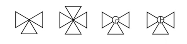
3-Way & 4-Way Valves (T-Port vs. L-Port)
Multi-port valves are used to divert or mix fluid streams. In a P&ID, extra triangles are attached to the core bowtie to signify the third or fourth port.
However, engineers must look closely at the internal markings or text codes next to the symbol. An L-Port (Diverting) configuration connects the center port to either the left or right port, but never both at once. A T-Port (Mixing/Diverting) can connect all three ports together or divert flow between two lanes. Missing this distinction during layout design can lead to incorrect flow routing during commissioning.
Protection & Safety Valves
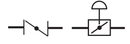
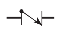
Check Valves
Check valves (also known as non-return or counter-flow valves) are used to automatically prevent fluid backflow within a system. On a P&ID, a check valve is typically represented by a small triangle or a diagonal line embedded in the pipeline, accompanied by a clear directional flow arrow. Its mechanical operation is driven entirely by the fluid’s own pressure: forward flow pushes the disc open, while backflow creates fluid backpressure that forces the disc tightly against the seat, instantly cutting off reverse flow and protecting critical upstream equipment such as pumps.
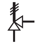
Safety Valves / Relief Valves
Pressure Safety Valves (PSVs) and Pressure Relief Valves (PRVs) serve as the ultimate line of defense for process piping and pressure vessels (such as boilers and storage tanks). On a P&ID, they are depicted by a distinct angular configuration (90-degree elbow discharge) with lines at the top representing the internal spring mechanism. When the internal system pressure exceeds the safety set point, the valve automatically pops open instantly to direct the overpressure fluid toward a safe zone (such as a flare system or a vent stack), preventing catastrophic physical explosions due to overpressurization.
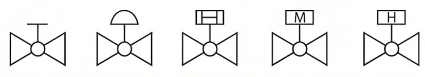
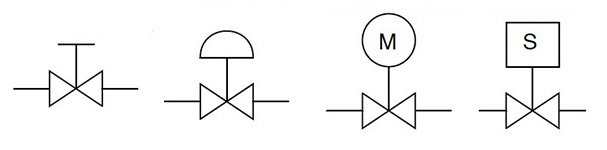
3. Automation and Actuator Symbols: Who is Driving the Valve?
In modern automated process plants, valves are rarely operated by handwheels alone. Instrument loops constantly drive valves to adjust positions based on real-time data. The shape mounted directly above the valve bowtie tells the engineer exactly how the valve is actuated.
| Actuator Type | P&ID Graphical Symbol Feature | Typical Industrial Application |
| Manual (Handwheel/Lever) | A simple “T-bar”, line, or small circle above the valve body. | Manual isolation, bypass loops, and maintenance blocks. |
| Pneumatic (Diaphragm/Piston) | A dome or square box containing a horizontal diaphragm line, often labeled with a “P” or an explicit air line connection. | High-speed, high-reliability process control loops. |
| Electric Motor (MOV) | A square box labeled with an “M” or “E”. | Large diameter pipelines, remote water distribution networks. |
| Solenoid Valve | A box featuring a zigzag coil symbol or marked with an “S”. | Quick on-off safety interlocking systems. |
4. Deciphering Valve Tags and Control Loops
A valve symbol on a P&ID is almost always accompanied by an identification tag inside or next to an instrument bubble. This tag follows a strict lettering hierarchy that defines its role in the automation loop:
- FCV (Flow Control Valve): Automatically adjusts its opening to maintain a specific flow rate target.
- PCV (Pressure Control Valve): Modulates up and down to regulate upstream or downstream system pressure.
- TCV (Temperature Control Valve): Adjusts fluid flow (such as cooling water or steam) based on temperature sensor feedback.
- SDV (Shutdown Valve): An automated safety valve that slams shut during an emergency.
These tags are linked directly to the plant’s centralized database, allowing engineers to quickly pull up the material composition, pressure rating, and vendor data sheet.
5. Advanced Reading: Fail-Safe Modes & End Connections
To fully understand a piping blueprint, you must look beyond the valve type and examine its operational logic and physical boundary connections.
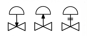
Fail-Safe Actions (FO, FC, FL)
When a plant loses instrument air or electrical power, automated control valves must automatically transition into a safe state to protect the facility.
- Fail Open (FO): The valve defaults to a fully open state (indicated by an upward-pointing arrow or the letters “FO”). This is common for cooling lines.
- Fail Closed (FC): The valve automatically shuts tight (indicated by a downward-pointing arrow or “FC”). This is a mandatory safety requirement in critical fire-safe and hydrocarbon zones to isolate fuel lines.
- Fail Last / Lock in Position (FL): The valve freezes in its exact position prior to power loss, keeping the process steady until power returns.
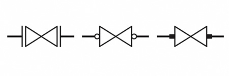
Pipeline End Connections
The way a valve joins a pipe dictates its pressure ratings, leak risks, and maintenance ease. Watch for these small line modifiers at the valve borders:
- Flanged (FLG): Parallel vertical lines at the tips of the bowtie with a small gap, denoting a bolted flange configuration that allows removal without cutting.
- Threaded (THRD): Small open circles or short intersecting lines, indicating a screwed semi-permanent joint.
- Welded (WLD): Filled black squares indicate a permanent socket weld, while hollow squares indicate a butt weld for high-pressure, zero-leakage configurations.
Conclusion & Engineering Checklist
Mastering valve symbols ensures seamless collaboration across design teams, procurement houses, and field installation crews. Remember that a P&ID is a logical topology map, not a physical scale drawing.
The size of a symbol does not reflect the actual valve dimensions, and its placement represents logical flow order rather than physical spatial positioning.