
In the design and construction of industrial fluid control systems, valve selection often dictates the operational efficiency and economic lifespan of the entire pipeline. During the Piping and Instrumentation Diagram (P&ID) review stage, one of the most critical debates faced by engineers and procurement managers is whether to specify Full Bore or Reduced Bore ball valves.
While they may look virtually identical externally, their internal geometry dictates flow dynamics, system efficiency, and ultimately, the long-term balance between Capital Expenditure (CAPEX) and Operating Expenses (OPEX).
This guide examines the core differences between these two valve types and provides a practical guide for your selection.
1. Technical Definitions & Mechanics
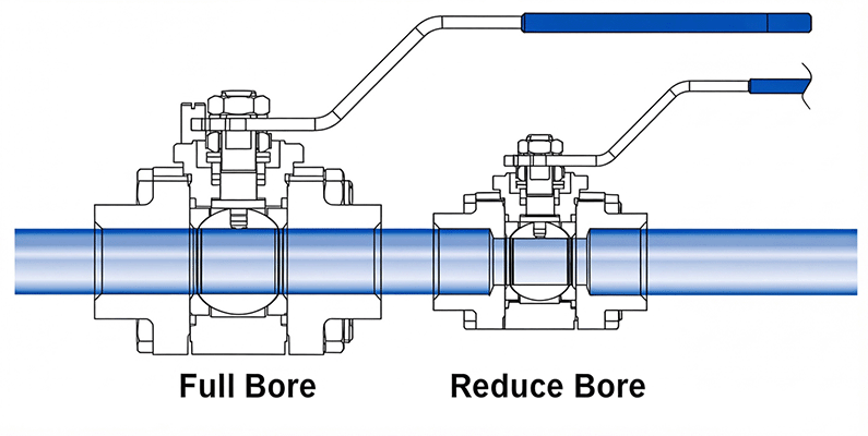
In fluid engineering, “bore” refers to the standardized internal diameter of a flow path within a valve. The fundamental distinction between full bore and reduced bore lies in the ratio between the internal diameter (ID) of the ball sphere and the ID of the connecting pipe.
Full Bore Ball Valve
- Structural Features: According to industry standards, the internal bore diameter of a full bore ball valve must align with the nominal internal diameter of the pipe (typically $\ge 95\%$).
- Fluid Performance: When the valve is fully open, the flow path remains consistent in width from inlet to outlet. The valve effectively becomes an extension of the pipe, resulting in zero flow restriction and virtually no pressure drop.
Reduced Bore Ball Valve
- Structural Features: The internal bore diameter is typically reduced by one or two pipe sizes compared to the nominal size of the connecting pipeline (typically $\le 85\%$). For example, a DN50 reduced bore valve houses a ball with an internal flow path equivalent to a DN40 pipe (approximately 38mm).
- Fluid Performance: As fluid passes through this constriction, it creates a localized “Venturi effect”—velocity increases while static pressure decreases, causing a permanent pressure drop across the valve.
2. Key Engineering Trade-offs
In real-world industrial applications, there is no single “better” valve; it is entirely a matter of balancing system requirements. Engineers must carefully evaluate trade-offs across four key dimensions:
Flow Coefficient and Pressure Drop
- Full Bore: It features an exceptionally high Flow Coefficient (Cv), nearly identical to a straight length of pipe. This means the local pressure drop is virtually zero, maintaining optimal system efficiency and significantly reducing upstream pumping energy.
- Reduced Bore: The narrowed flow path creates an intentional flow restriction. According to hydraulic principles, reducing the internal diameter by just 25% can decrease flow capacity by approximately 40% to 50%. In long-distance transmission lines, extensive use of reduced bore valves can lead to massive cumulative pressure losses, significantly driving up long-term energy consumption.
Actuation Torque and Sizing
- Full Bore: The larger ball size results in a greater surface area in contact with the valve seats. Consequently, the operating torque required to open and close the valve is significantly higher, meaning it must be paired with larger, more robust pneumatic or electric actuators.
- Reduced Bore: A smaller ball reduces the material contact area, which lowers the operating torque substantially. This allows for a scaled-down actuator selection, drastically reducing the overall cost of automated control units.
Media Suitability and Pipeline Cleaning
- Full Bore: The unobstructed straight-through flow path makes it the only viable choice for handling high-viscosity fluids (crude oil, heavy oil, asphalt), slurries containing solid particles, or media prone to slagging. More importantly, full bore designs are a mandatory requirement for pipelines requiring routine cleaning and inspection via pipeline pigs.
- Reduced Bore: These valves are strictly suited for clean gases (natural gas, steam, compressed air) or low-viscosity liquids (clean water). If used with viscous or particle-laden media, material is highly prone to accumulating and scaling at the internal “steps,” leading to severe erosion or seat leakage.
Weight and Capital Expenditure (CAPEX)
- Full Bore: Featuring a robust valve body and an oversized ball, these valves require more raw materials and complex manufacturing. As a result, their purchase cost is typically 20% to 40% higher than equivalent reduced bore versions. Furthermore, they are roughly 30% heavier, adding substantial load stress to pipe supports.
- Reduced Bore: Characterized by a compact and lightweight design. This lightweight construction not only slashes initial procurement costs by nearly one-third but also offers great convenience during long-distance transportation, field installation, and deployment within tight skid-mounted systems.
3. Quick Comparison: Full Bore vs. Reduced Bore
For quick engineering reference, the key performance characteristics of both designs are summarized below:
| Feature / Dimension | Full Bore Ball Valve | Reduced Bore Ball Valve |
| Internal Flow Path Design | Identical to pipe diameter ($\ge 95\%$) | Smaller than pipe diameter ($\le 85\%$, usually 1 size down) |
| Fully Open Flow Resistance | Minimal (virtually zero, acts as straight pipe) | Noticeable (creates Venturi effect) |
| Localized Pressure Drop | Negligible | Measurable (approx. $0.1 \sim 0.5 \text{ bar}$) |
| Weight and Dimensions | Heavier, larger footprint | Lighter, compact design (approx. 30% weight reduction) |
| Initial Purchase Cost | Higher (20%–40% price premium) | Lower (highly economical) |
| Operating Torque Requirement | Higher (requires larger actuators) | Lower (allows smaller, economical actuators) |
| Pipeline Pigging Operations | Fully supported (mandatory requirement) | Strictly prohibited (will trap the pig) |
| Recommended Media | Crude oil, slurries, viscous or solid-laden media | Natural gas, clean water, steam, compressed air |
Technical Support & Consultation
As a professional fluid control equipment supplier, we maintain a comprehensive product portfolio, providing high-quality Full Bore Ball Valves and Reduced Bore Ball Valves compliant with various international standards.
Optimizing valve selection for piping systems requires a comprehensive hydraulic evaluation factoring in pressure, temperature, media characteristics, and automation requirements. Our engineering team is fully equipped to review your specific process data sheets and budgetary constraints to deliver customized valve configurations and actuator sizing solutions. Please feel free to contact our technical support team via phone or email for professional technical consultations and product quotations.