
As a core component in modern industrial fluid control, the ball valve’s structural evolution and sealing mechanism directly determine the safety and longevity of pipeline systems. This article provides an in-depth analysis of the core construction, classification logic, and engineering selection criteria for ball valves.
I. Detailed Analysis of Ball Valve Construction
The performance of a ball valve depends on the precise coordination and mechanical design of its key components:
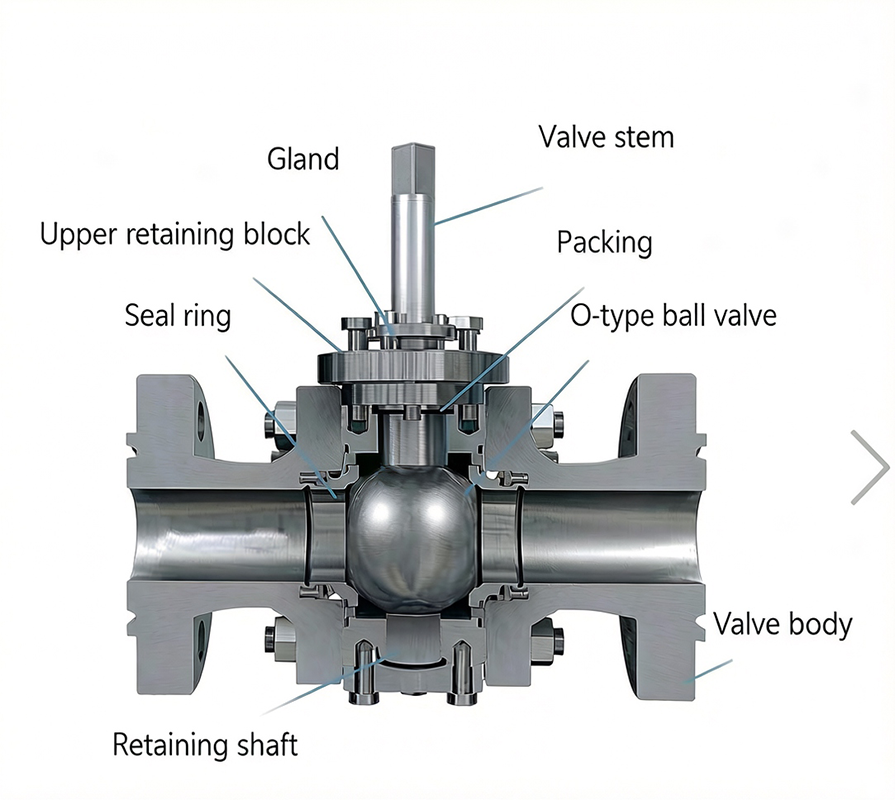
1. Valve Body: The Foundation of Structural Integrity
The valve body serves as the framework for the valve and must meet pressure requirements for various Classes.
- Manufacturing Process: Forged valve bodies feature a dense metal structure, offering superior fatigue resistance compared to cast bodies, making them suitable for high-pressure, mission-critical pipelines.
- Structural Connection: The one-piece design eliminates body joint seams, minimizing potential external leakage points. The three-piece split structure facilitates maintenance, allowing for the replacement of internal components from the side without disconnecting the entire pipeline flange.
- Material Matching: Material selection must be precisely matched to the chemical nature of the media (e.g., H2S content) and operating temperature, typically utilizing ASTM A105 (carbon steel) or A182 F316 (stainless steel).
2. Ball: The Core of Flow Control
The geometric precision of the ball surface is the basis for tight shutoff.
- Dimensional Tolerances: The sphericity of the ball must be controlled to the micron level, with surface mirror polishing (Ra 0.2–0.4 μm) to reduce friction and ensure uniform sealing pressure distribution.
- Flow Port Design: The Full Port design minimizes pressure drop and allows for pigging operations; the Reduced Port design effectively lowers operating torque in applications where pressure drop is not critical, thereby reducing actuator costs.
- Hardening Treatment: To withstand high erosion and particulate media, ball surfaces are frequently treated with hard chrome plating, Stellite alloy spraying, or tungsten carbide to resist fluid erosion.
3. Stem & Packing: Barrier Against External Leakage
The packing assembly is the most vulnerable point for external leakage; high-performance designs include:
- Blowout-proof Design: The stem shoulder is positioned inside the valve body, ensuring that the stem is locked under high-pressure media, eliminating the risk of ejection.
- Packing Seal Combination: Utilizing a “V-ring PTFE + Flexible Graphite” composite structure, this design balances chemical compatibility with high-temperature deformation resistance.
- Live Loading Technology: The packing gland assembly utilizes disc springs to provide “self-compensation.” When packing material shrinks due to thermal cycling or wear, the springs automatically provide continuous axial preload, ensuring stable long-term sealing.
4. Seat: Sealing and Preload Mechanisms
The seat is critical for tight shutoff, featuring:
- Spring-assisted Preload: The rear of the seat is equipped with coil or wave springs to maintain initial contact with the ball under very low or zero line pressure, providing low-pressure sealing capability.
- Piston Effect and Self-sealing: The seat design utilizes a “piston effect.” When upstream pressure is applied, the differential pressure pushes the seat against the ball, increasing sealing pressure as line pressure rises.
- Relief Function: The SPE (Self-Relieving Seat) design allows for automatic pressure relief from the valve cavity to the upstream pipeline when pressure increases due to thermal expansion, preventing shell rupture.
- Hard Sealing Design: For high-temperature, high-pressure, or particulate-laden media, the seat utilizes surface hardening processes (e.g., HVOF spraying) to achieve metal-to-metal contact with precise matching lapping.
II. System Classification
- Floating Ball Valve: The ball relies on fluid pressure to shift slightly, pressing against the downstream seal ring to achieve sealing. Suitable for small-to-medium diameters and low-to-medium pressures.
- Trunnion Mounted Ball Valve: The ball is supported by upper and lower trunnions, preventing movement under fluid pressure. Sealing is completed by spring-assisted floating seats pressed against the ball. Suitable for large diameter, high-pressure applications.
- Lift-Plug Ball Valve: Employs a mechanical mechanism to “lift before turn,” completely eliminating friction and wear during opening and closing. This is the optimal solution for abrasive or particulate-laden media.
III. Special Design and Safety Functions
- Fire-safe Design: Compliant with API 607 standards; if soft seals are destroyed during a fire, the ball contacts the metal lip on the valve body, forming a secondary backup seal to prevent massive leakage of flammable media.
- Redundant Sealing Technology (DBB/DIB): Through dual-seat sealing, it provides higher safety redundancy and online sealing verification capabilities.
IV. Industrial Application and Selection Criteria
| Application Scenario | Selection & Configuration Recommendations |
| Long-distance Oil/Gas Pipelines | Trunnion mounted, all-welded structure, Full Port (supports pigging) |
| Refined Oil Transport/Storage | Flanged ball valves |
| Metallurgical Oxygen Pipelines | Trunnion mounted ball valves with strict degreasing treatment |
| Catalytic Cracking Units | Lift-plug ball valves (to handle particle erosion) |
| High Temperature (>200°C) | Metal-to-metal seal ball valves (with flexible graphite packing) |
| Precision Flow Control | V-port ball valves (paired with high-precision actuators) |
Note: This article covers only the fundamental construction and selection logic of ball valves. We will continue to provide in-depth supplements on advanced technical knowledge in future technical columns. Stay tuned.