
In the modern industrial fluid control pipeline system, ball valves are the most widely adopted quarter-turn rotary valves. While all ball valves utilize a rotary ball and stem to modulate flow, their internal sphere configurations differ significantly based on specific working conditions.
This comprehensive guide delivers a deep dive into the engineering structures, dynamic seating systems, and distinct operational advantages of the two industry pillars: O-Port Ball Valves (On-Off/Isolation Service) and V-Port Ball Valves (Precision Flow Control and Slurry Modulation).
Part 1: Comprehensive Anatomy of the O-Port Ball Valve Structure
What is an O-Port Ball Valve?
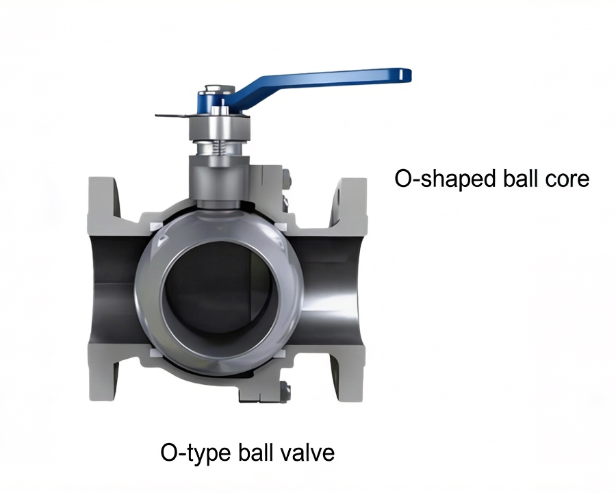
The O-port ball valve features a standard cylindrical bore machined straight through a spherical ball element. The internal diameter (ID) of this bore exactly matches the pipeline’s inside diameter, commonly referred to as a Full-Bore (Full-Flow) design. When the actuator rotates the valve stem 90 degrees, the fluid flows through a straight, unobstructed pipe-like channel, minimizing turbulence and friction losses.
Five Core Engineering Advantages for Process Pipelines
1. Near-Zero Fluid Resistance (Lowest Flow Friction Coefficient)
Whether configured as full-bore or reduced-bore, O-port ball valves exhibit the lowest flow resistance coefficient among all industrial valves. In a full-bore configuration, the fluid port profile is a perfect extension of the pipeline. The pressure drop (Delta P) across a fully opened O-port ball valve is practically identical to a straight piece of pipe of the same length, drastically saving pump power across long-distance oil, natural gas, and water treatment lines.
2. Rapid Quarter-Turn On-Off Actuation
The mechanical stroke of the O-port ball requires a precise 90-degree rotation from a fully closed state to a fully open state. This makes it ideal for emergency shutdown valves (ESDVs) and rapid isolation automation lines.
3. Advanced Elastomeric Dynamic Sealing Performance
Most conventional O-port ball valves utilize resilient elastomeric seat rings—such as PTFE, TFM, or Devlon—classifying them as soft-seated ball valves. The inherent elasticity of these polymers compensates for minor micro-roughness on the ball surface, consistently achieving zero-leakage rates compliant with ISO 5208 Class A and API 598 standards.
4. Extended Operational Service Life via Self-Lubricating Materials
Due to the excellent self-lubricating properties of PTFE and modified fluoropolymers, the friction coefficient (µ) between the polished valve ball and the seat ring is remarkably low. Combined with high-grade manufacturing surface grinding (achieving roughness style less than or equal to 0.8µm Ra), internal wear is minimized, ensuring a stable, low operating torque even after thousands of cycles.
5. High-Integrity Safety and Reliability Features
- Anti-Blowout Stem Design: The valve stem is back-seated and inserted from the inside of the valve body cavity. Under high pipeline pressures, the fluid pressure forces the stem shoulder against the body seal rather than pushing it outward, preventing dangerous stem blowouts even if the packing gland is loosened.
- Anti-Static and Fire-Safe Designs: Integrated metallic springs maintain continuous electrical continuity between the ball, stem, and valve body to discharge static buildup. Fire-safe configurations (compliant with API 607 / API 6FA) incorporate a secondary metal seat that seals against the ball if the soft seat melts during a fire.
Ideal On-Off Automation Applications
The flow characteristic of an O-port ball valve is Quick-Opening. It acts as an unrestricted, straight-pipe conduit when fully opened, providing optimal bi-directional sealing and exceptional “self-cleaning” properties. It is highly recommended for two-position (On-Off) isolation services in water transmission, oil and gas distribution, and clean chemical lines.
Part 2: Advanced Anatomy of the V-Port Regulating Ball Valve
What is a V-Port Ball Valve?
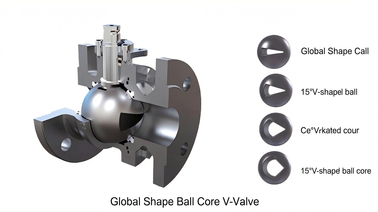
Unlike the standard O-port, a V-port ball valve utilizes a segmented sphere with a precision-machined “V” shaped profile cut into the flow port. It is explicitly engineered for throttling, modulating, and precise flow control rather than simple isolation. Due to its unique geometry, V-port modulating valves are typically single-seated, uni-directional valves.
High-Performance Characteristics for Demanding Working Conditions
1. True Equal-Percentage Flow Characteristic
The critical limitation of standard ball valves is their poor performance in throttling applications; slight openings cause severe scouring and cavitation. The V-notch geometry solves this by modifying the opening area proportionally. As the V-ball rotates open, the flow capacity (Cv) increases exponentially, delivering highly stable, sensitive, and linear flow regulation with an exceptionally wide turndown/control range (up to 300:1 ratio).
2. Severe Shearing Action and Scissor-Like Self-Cleaning
During the quarter-turn closing stroke, the sharp, hard edge of the V-notch ball slides against the metal valve seat with a mechanical wedge action. This creates a powerful shearing effect (guillotine action) that cuts clean through high-viscosity fluids, suspended crystals, paper pulp, and tough fibrous debris without clogging or jamming the internal cavity.
3. Dual-Bearing Heavy-Duty Structure for Low Operating Torque
High-end industrial V-port regulating valves adopt a rugged trunnion-mounted or dual-shaft bearing design. By fixing the valve ball securely along a vertical axis, the high lateral differential pressure forces are absorbed by the heavy-duty upper and lower bearings. This configuration lowers the starting friction, minimizes operating torque, and significantly improves control sensitivity and response speeds.
4. Stable Metal-to-Metal Point Contact Engineering
The body, bonnet, and seat of a high-performance V-port ball valve feature rugged metal-to-metal contact structures. Utilizing tough pre-loaded seat springs behind the metal seat ensures a tight mechanical seal while compensating for thermal expansion and pressure fluctuations, making it ideal for controlling high-temperature steam, gases, and corrosive slurries.
Modulating and Control Capabilities
The V-port ball valve operates as an advanced straight-through rotary control valve. Typically integrated with pneumatic or electric actuators and intelligent smart electro-pneumatic valve positioners, it translates 4-20mA signals into precise valve positioning. Its compact physical footprint, high flow coefficients (Cv), and vertical/horizontal flexibility make it the absolute premier choice for pulp and paper, mining slurries, environmental wastewater treatment, and steam modulation sectors.
Summary: Technical Engineering Comparison Matrix
For optimal engineering procurement, reference this comparison chart derived from API 6D and ASME B16.34 standards:
| Engineering Parameter | O-Port Ball Valve Structure | V-Port Regulating Ball Valve |
| Primary Functional Design | On-Off Service / Tight Isolation | Modulating / Precision Flow Control |
| Inherent Flow Characteristic | Quick-Opening | Approximate Equal-Percentage |
| Sealing System Orientation | Typically Bi-Directional | Uni-Directional (Single-Seat) |
| Media Compatibility | Clean Liquids, Gases, Low-Viscosity Fluids | Fibrous Pulp, Slurries, Viscous Media, Gases |
| Shearing/Cutting Capability | None (Susceptible to fiber jamming) | Excellent (Scissor-like cutting action) |
| Turndown Control Ratio | Low (Typically 50:1, poor control) | Exceptionally High (Up to 300:1) |
| Typical Seating Material | Soft Seating (PTFE / TFM / NBR) | Hard Metal Seating (Stellite / WC Hardfaced) |
By meticulously matching your pipeline’s medium viscosity, target flow characteristic, and velocity to the correct internal ball geometry, you can optimize plant safety, reduce cavitation wear, and maximize system service longevity.