In modern fluid automation and process engineering, selecting the optimal actuated valve type directly impacts system efficiency, plant safety, and overall piping longevity. Engineers and procurement professionals frequently navigate a critical decision matrix when isolating or modulating flow: Should they deploy an electric ball valve, a solenoid valve, or an electric butterfly valve? While solenoid valves excel in instantaneous micro-switching and butterfly valves offer compact economics for giant pipelines, the electric ball valve remains the most robust choice for high-pressure durability, zero-pressure-drop continuity, and dirty media tolerance.
This comprehensive technical guide provides an objective engineering analysis of electric ball valves, detailed through mechanical anatomy, electrical control logic, international standards, and cross-type technical comparisons.
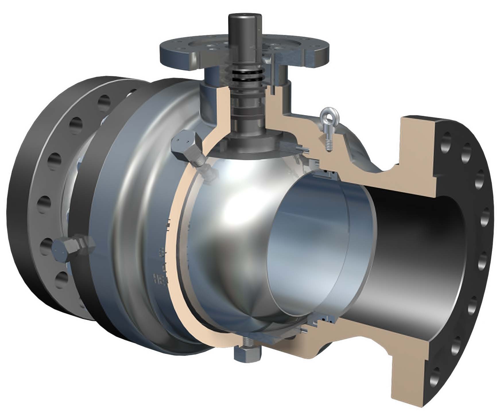
1. Internal Anatomy and Mechanical Operating Principle
Evaluating the performance of an electric actuated ball valve under heavy pipeline stress requires a complete understanding of its structural configuration. The fully automated quarter-turn assembly comprises four distinct functional sections:
The Valve Body and Flow Port Configuration
The pressure-retaining housing is typically forged or cast from high-grade Brass, Stainless Steel (SS304/SS316), or chemical-resistant PVC. Inside the body, a highly polished sphere (the ball) is suspended between two resilient polymer seats (typically reinforced PTFE). The ball is machined with a continuous straight hole through its center, known as the bore or port.
When a full-bore (full-port) electric ball valve is fully opened, the internal channel matches the inside diameter of the surrounding pipe precisely. Fluid flows through a straight, unobstructed path, experiencing virtually no directional changes or internal friction. This yields an exceptionally high flow coefficient (Cv) and keeps system pressure drop close to zero.
The Electric Actuator and High-Torque Motor
Mounted securely above the valve body is the electric actuator—the protective housing for the synchronous control circuit board and a specialized electric motor (AC or DC). The actuator translates electrical signals into precise rotary mechanical force to turn the internal valve stem.
Multi-Stage Gear Reduction Train
Because compact electric motors rotate at high speeds with relatively low torque, a multi-stage gear reduction train constructed from hardened steel or brass gears is integrated into the actuator. This gear train reduces the output rotational speed while exponentially multiplying the torque rating. This ensures the actuator has sufficient torque to overcome tight seat friction and shear through any media buildup, even after the valve has sat completely idle for extended periods.
Internal Limit Switches and Travel Control
Every reliable electric ball valve utilizes integrated mechanical or electronic limit switches. When the actuator rotates the valve stem exactly 90 degrees (quarter-turn), a precision-machined cam triggers the internal limit switch. This instantly interrupts the power supply to the motor, stopping all rotation. The internal gear train then mechanically locks the valve securely in that open or closed position without drawing any further electrical current.
2. Cross-Type Technical Comparison: Ball vs. Solenoid vs. Butterfly
To justify the selection of an electric ball valve, engineers must evaluate how its core technical parameters compare againstalternative automated valves under specific operational strains.
Water Hammer Mitigation: Electric Ball vs. Solenoid Valves
Solenoid valves utilize magnetic coils to snap open or shut within milliseconds. When a high-velocity fluid is stopped instantly, the kinetic energy converts into a massive pressure spike, causing a shockwave known as water hammer that fractures pipe joints. Electric ball valves close gradually—typically over 3 to 15 seconds. This slow, controlled closure cushions the fluid momentum, eliminating water hammer entirely in commercial plumbing and high-flow networks.
Fluid Continuity & Flow Coefficient (Cv): Electric Ball vs. Electric Butterfly Valves
While an electric butterfly valve is highly economical for large lines, its internal disc (the butterfly plate) permanently sits dead-center in the fluid stream even when fully open. This obstruction creates turbulent flow, causes a noticeable pressure drop, and prevents the usage of pipe cleaning pigs. A full-bore electric ball valve, offering a 100% unobstructed channel, delivers a vastly superior flow coefficient (Cv) and zero flow resistance.
Media Tolerance and Particulate Handling
Solenoid valves rely on tiny, precise internal pilot holes and delicate rubber diaphragms to balance pressure. If the fluid contains rust, sand, or mineral scaling, these pilot holes clog immediately, causing the valve to stick. Electric butterfly valves are also prone to gathering fibrous debris around the disc edge, causing internal seat leaks. The rotational sweeping action of an electric ball valve across its seats naturally shears and clears away solid particles, making it highly tolerant of dirty liquids, viscous oils, and light slurries.
Energy Efficiency and Heat Management
A standard solenoid valve requires a continuous electrical current flowing through its copper coil to hold its position against line pressure, leading to continuous power consumption and intense heat buildup (frequently causing coil burnout). Electric ball valves and electric butterfly valves only consume electrical power during the few seconds it takes to change positions. Once the limit switch is triggered at 90 degrees, they draw zero power while holding their open or closed state.
3. Advanced Wiring Options and Control Logic
Integrating an electric ball valve into an automated system requires matching the actuator’s wiring configuration to the control panel’s output logic. Modern industrial setups rely on several standardized configurations:
- 2-Wire Control (Reverse Polarity or Auto-Return): Utilizes reverse polarity for DC power or an auto-return capacitor circuit. Ideal for simple “power-to-open, power-off-to-close” automation lines.
- 3-Wire Control (SPDT Control): The standard configuration for commercial building HVAC and plumbing networks. It features one permanent common wire, one dedicated open control wire, and one dedicated close control wire. The motor stops automatically at the end of travel via internal limit switches.
- 5-Wire Control with Position Feedback: Includes the standard 3-wire control lines plus two auxiliary signal lines connected to internal dry-contact micro-switches. These auxiliary lines report the live open or closed status directly back to a remote PLC control room, eliminating guesswork.
- Modulating Type (Proportional Control): Designed for precise flow regulation. It requires constant power wires combined with a dedicated pair for an analog input/output control signal (typically 4-20mA or 0-10V) to adjust the valve to any partial angle (e.g., 45° open).
Advanced Fail-Safe Supercapacitors
In critical industrial environments, a sudden loss of facility power can lead to system damage if a valve remains stuck in an improper position. To counter this, advanced electric ball valves utilize an auto-return fail-safe mechanism powered by built-in supercapacitors. During regular operation, the incoming power keeps the capacitor charged. The moment power drops, the capacitor discharges its stored electrical energy to the motor, driving the valve safely to its pre-programmed default state (normally closed or normally open).
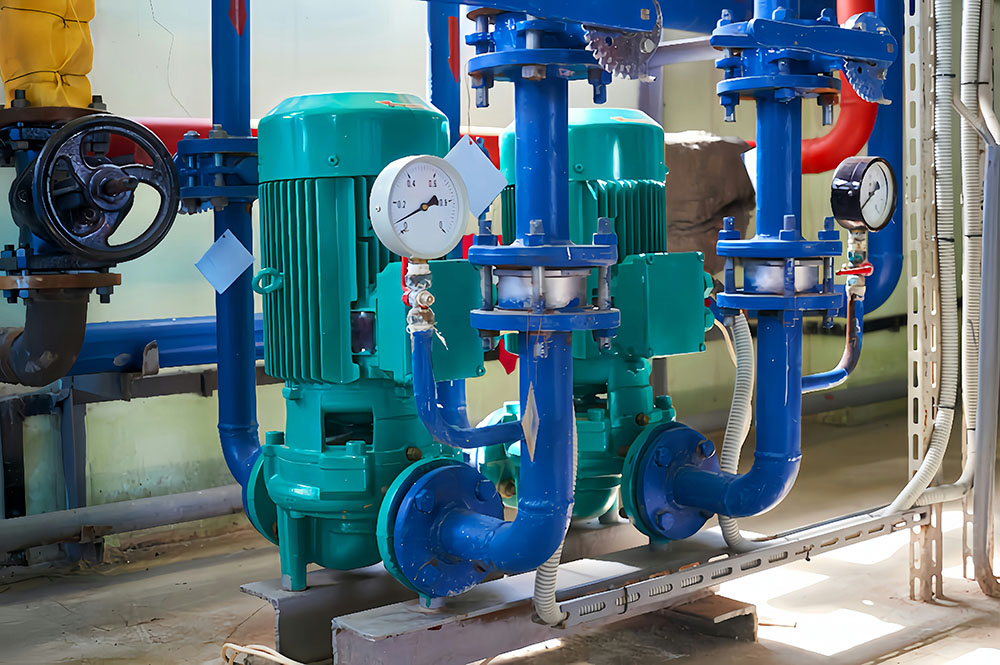
4. Primary Application Environments and Industry Settings
Electric ball valves are highly effective across demanding, automated industrial settings:
- Commercial HVAC Zone Control: In large-scale heating and cooling installations, modulating electric valves alter the flow rate of hot or chilled water by stopping at precise angular positions based on continuous temperature feedback signals.
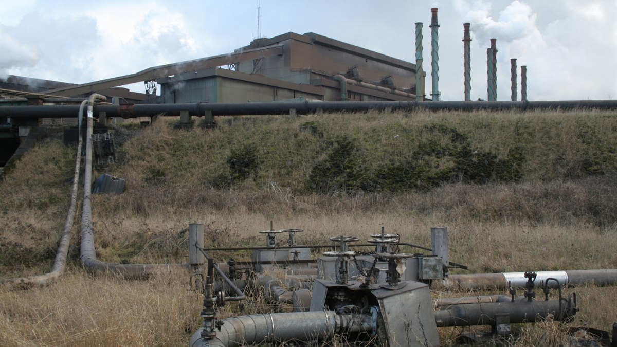
- Water Treatment and Desalination: Reverse osmosis (RO) systems and wastewater plants utilize large-diameter pipelines. Electric ball valves handle these high-flow water treatment lines reliably, resisting the corrosive effects of brackish water when cast in SS316.
- Industrial Process Automation: For handling acids, caustic solutions, and solvents, stainless steel or PVC electric ball valves provide secure, automated shut-off where manual intervention is dangerous or impractical.
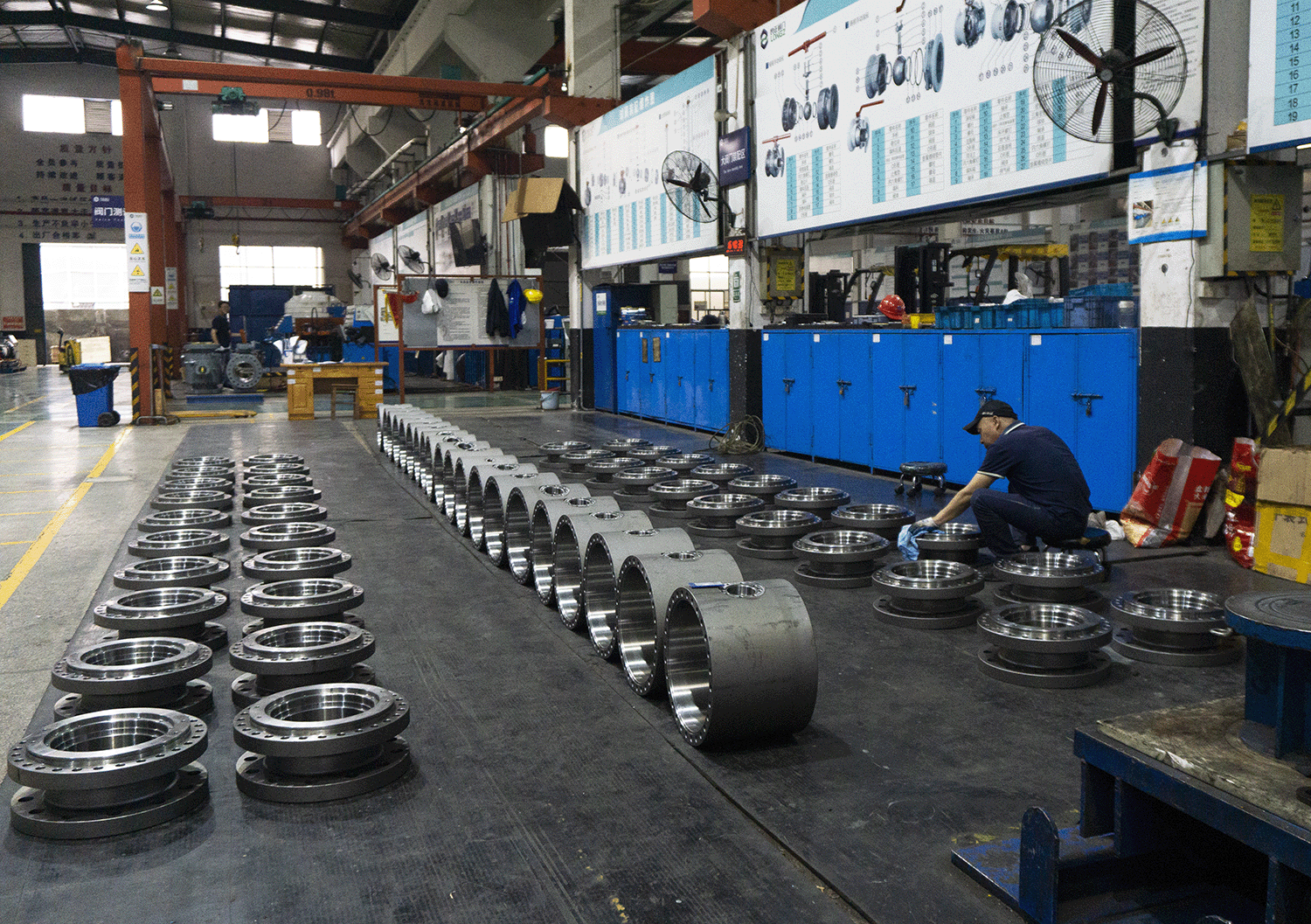
5. International Manufacturing Standards and Engineering Compliance
For international trade and industrial engineering projects, compliance with recognized manufacturing specifications is mandatory to ensure safety and interchangeability.
Valve Body Design Standards
- ASME B16.34: Dictates the pressure-temperature ratings, wall thicknesses, and material dimensions for cast and forged valves used in high-pressure applications.
- API 6D: Developed by the American Petroleum Institute, this standard defines the stringent manufacturing and testing parameters for pipeline valves used in critical energy infrastructure.
- Thread and Flange Specifications: Valve connections must strictly adhere to regional standards, such as NPT (National Pipe Tapered) for North American piping, or G threads (BSP) and DIN flanges for European installations.
Actuator and Enclosure Standards
- IP67 / IP68 Enclosure Ratings: Industrial actuators must withstand environmental moisture. An IP67-rated enclosure is completely dust-tight and verified to withstand temporary submersion in water, preventing electronic short-circuits in outdoor or washdown environments.
- NEMA 4 / 4X Standards: For the US market, NEMA 4 enclosures guarantee protection against windblown dust, rain, and hose-directed water, while 4X adds strict requirements for corrosion resistance.
6. Frequently Asked Questions (FAQ)
Q1: Can an electric ball valve be installed outdoors?
Yes, provided the electric actuator carries an appropriate environmental enclosure rating. For outdoor environments exposed to rain, windblown dust, or washdown procedures, you must select an actuator with at least an IP67 or NEMA 4 rating. It is also recommended to install a simple sunshield to protect the electronic housing from long-term UV degradation and extreme temperature spikes.
Q2: What happens to an electric ball valve during a sudden power failure?
It depends on the actuator type. A standard electric ball valve will stay frozen in its last position when power is lost because the mechanical gears lock the stem. However, if your system requires a safety backup, you should choose a Fail-Safe Electric Ball Valve. These units contain built-in supercapacitors that store energy during normal operation and use it to automatically drive the valve fully closed or fully open during a power outage.
Q3: How do I know if I need a Full-Bore or a Reduced-Bore electric ball valve?
If your application is sensitive to pressure drops or involves fluid with suspended particulates (like wastewater or light slurries), you should choose a Full-Bore (Full-Port) design. In a full-bore valve, the internal opening matches the pipe’s diameter perfectly, resulting in zero flow restriction. Reduced-bore valves have a smaller internal channel; they are more economical and lighter but create higher friction and a noticeable pressure drop.
Q4: Why is my electric actuator overheating or stalling?
Actuator stalling is usually caused by insufficient torque redundancy or pipeline debris. Over time, mineral scaling or chemical particulates can build up on the valve seats, significantly increasing the torque required to turn the ball. If the actuator’s torque rating was selected without a proper safety margin (we recommend at least a 30% buffer), the motor will struggle and overheat. Installing an upstream Y-strainer and choosing a higher-torque actuator will resolve this issue.